5+ Diagram Of Pulley System

Draw A Diagram To Show A Block And Tackle Pulley System Having A Velocity Ratio Of 3 Marking The Direction Of Load L Effort E And Tension T
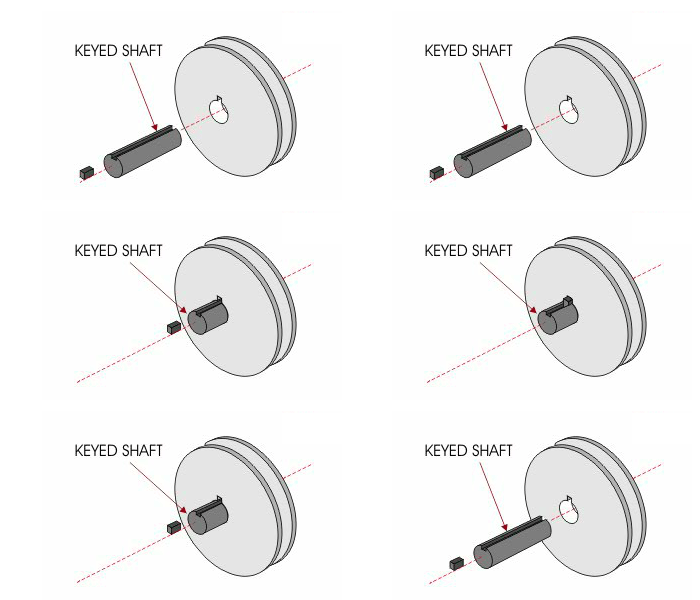
Robotic Mechanisms Pulley Systems 51005 Robotpark Academy

3400 Series Hub Mount Round Belt Pulley 14mm Bore 32mm Pd Gobilda Gb 3400 0014 0032 Core Electronics Australia
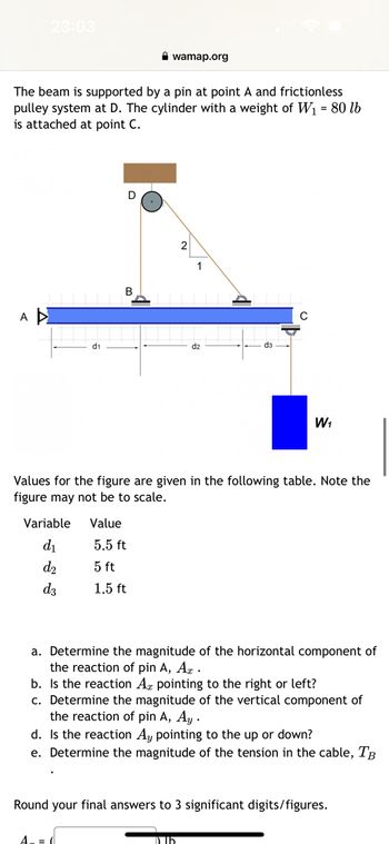
Answered The Beam Is Supported By A Pin At Point Bartleby

5 X Black Gt2 Pulley 20t 5mm Bore For Creality Ender 3 3s Cr 10 Cr 10s 3d Printer Parts 6mm Wide Belt 20 Teeth 2gt Stepper Motor Pulley Amazon De Business Industry Science

A Pulley System Has A Velocity Ratio 5 Draw A Neat Labelled Diagram Of The Pulley System To Lif Youtube
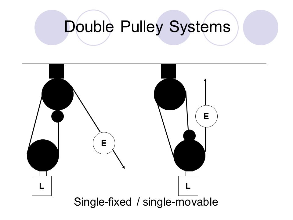
How To Diagram A Pulley System Anchor Point The Anchor Point Should Be A Solid Black Box Fixed To A Surface Ppt Download
![]()
The Pulley System It S 4 Types Applications Working Pdf Design Engineering

How To Diagram A Pulley System Anchor Point The Anchor Point Should Be A Solid Black Box Fixed To A Surface Ppt Download
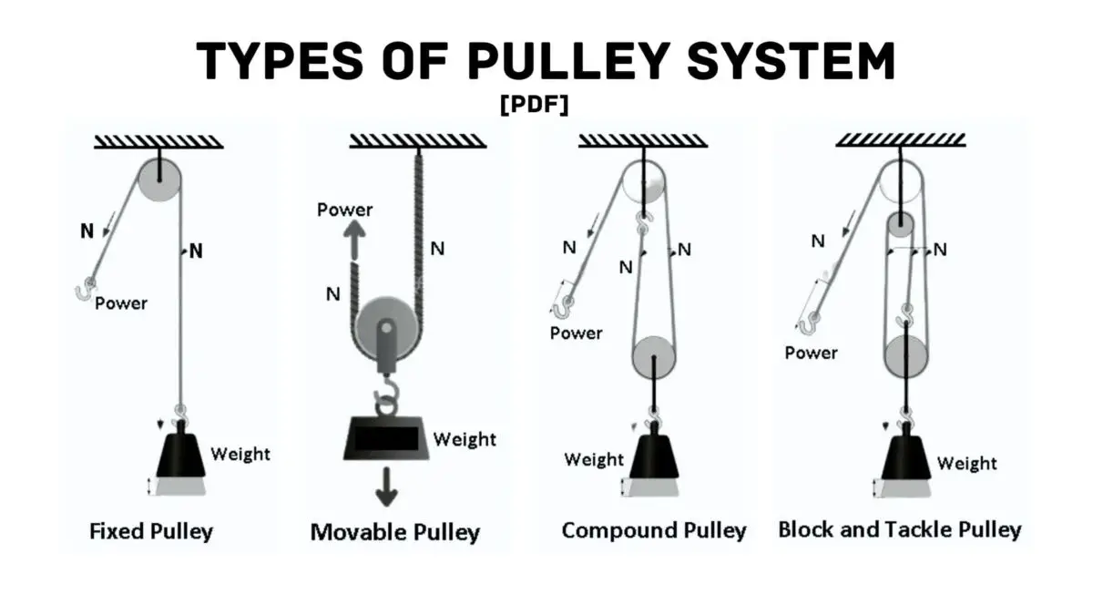
What Are Different Types Of Pulleys With Their Uses Pdf

Get Answer 08 3 Consider The System Shown In The Diagram The Pulley Is Transtutors
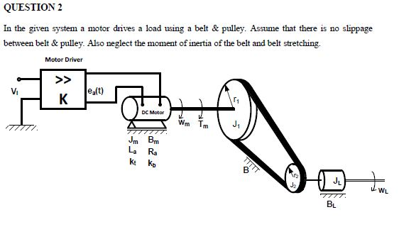
Question 2 In The Given System A Motor Drives A Load Chegg Com

46 405 Pulley Images Stock Photos 3d Objects Vectors Shutterstock

A Block And Tackle Pulley System Has A Velocity Ratio 5 Draw A Labelled Diagram Of This System In Your Diagram Indicate Clearly The Points Of Application And The Directions Of The

Diagram Of A Pulley System With Arrows Download Scientific Diagram
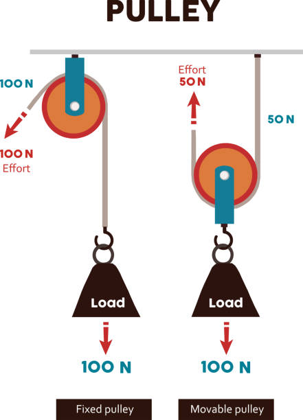
90 Pulley Diagram Stock Photos Pictures Royalty Free Images Istock

Pulley System Stock Illustrations 920 Pulley System Stock Illustrations Vectors Clipart Dreamstime

Steppers And Teethed Pulleys 23 By Madmark2150 Motors Mechanics Power And Cnc Arduino Forum